Wednesday, March 13, 2019

UCI :

UCI stands for Uplink Control Information. UCI is transmitted on PUCCH. It can even be multiplexed and sent over PUSCH.

UCI includes SR (Scheduling Request), HARQ-ACK, CSI (Channel State Information).

UE has a possibility to transmit one or two PUCCHs on a serving cell in different symbols within a slot, in such cases at least one of the two PUCCHs should be Format 0 or Format 2.

CRC for UCI bits >= 360 would be 11, for other cases UE determines based on UCI bits.

PUCCH resource sets for UCI transmission can be signaled to UE either by dedicated PUCCH configuration or by common PUCCH configuration.

Dedicated PUCCH Resource Config is via  PUCCH-ResourceSet in PUCCH-Config
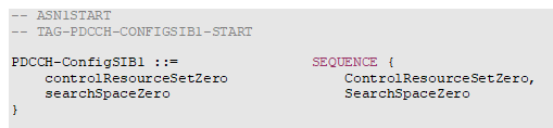
Common PUCCH Resource Set is via pucch-ResourceCommon.

PUCCH Resource Sets via pucch-ResourceCommon :


Index
PUCCH format
First symbol
Number of symbols
PRB offset
Set of initial CS indexes
0
0
12
2
0
{0, 3}
1
0
12
2
0
{0, 4, 8}
2
0
12
2
3
{0, 4, 8}
3
1
10
4
0
{0, 6}
4
1
10
4
0
{0, 3, 6, 9}
5
1
10
4
2
{0, 3, 6, 9}
6
1
10
4
4
{0, 3, 6, 9}
7
1
4
10
0
{0, 6}
8
1
4
10
0
{0, 3, 6, 9}
9
1
4
10
2
{0, 3, 6, 9}
10
1
4
10
4
{0, 3, 6, 9}
11
1
0
14
0
{0, 6}
12
1
0
14
0
{0, 3, 6, 9}
13
1
0
14
2
{0, 3, 6, 9}
14
1
0
14
4
{0, 3, 6, 9}
15
1
0
14
{0, 3, 6, 9}

Wednesday, February 6, 2019

Physical Uplink Control Channel (PUCCH) :

Similar to LTE, 5G NR PUCCH carriers the Uplink Control Information (UCI) in uplink.

Based on the PUCCH duration and the Payload size, 5G NR defines 5 PUCCH formats, as shown below.


PUCCH format
Length in OFDM symbols
Number of bits
0
1 – 2
≤2
1
4 – 14
≤2
2
1 – 2
>2
3
4 – 14
>2
4
4 – 14
>2

*Short PUCCH format of more than 2 UCI bits frequency multiplex UCI and DMRS
* Long PUCCH formats time multiplex UCI and DMRS

If Intra-slot frequency hopping is configured for PUCCH formats 1,3 or 4, the number of symbols in the first hop is given as |_ PUCCH OFDM symbols/2_|    (Floor of).

UCI can be multiplexed in PUSCH when both UCI and PUSCH transmissions coincide in time. Multiplexing can be done in two ways.

1. Puncturing 
2. Rate Matching

An UCI with 1 or 2 bit HARQ ACK feedback multiplexed by puncturing PUSCH. In rest of the cases multiplexing done by Rate Matching PUSCH.

UCI carries ;

1. CSI (Channel State Information like CQI, PMI, RI, CSI-RS ..etc)
2. ACK-NACK
3. SR (Scheduling Request)

* Transform Precoding is applied to long PUCCH.

Some Important collision cases :

1. If an UE having a PUSCH transmission that overlaps with a PUCCH which includes positive SR, 
    then UE should drop PUSCH.

2. If the UE transmitting PUCCH with CSI reporting with overlapping PUSCH, then UE should multiplex PUSCH with CSI reporting.

3. UE should not multiplex PUSCH transmission with UCI when the SCS of PUSCH is less than SCS of PUCCH.

4. UE should not detect the DL DCI for PDSCH reception or SPS release and indicating PUCCH resource to transmit HARQ-ACK in a slot if the UE already detected a DCI format scheduling PUSCH with HARQ-ACK multiplexing.

5. If an UE multiplex Aperiodic CQI in a PUSCH, and if there is a collision with PUCCH carrying UCI with HARQ-ACK, then UE should multiplex HARQ-ACK with PUSCH and drop PUCCH.

6. UE having multiple PUSCHs configured in a slot on serving cells, the first PUSCH scheduled by DCI 0_0 or DCI 1_0 and the second configured by UL SPS , UE should multiplex UCI on first PUSCH (not on SPS PUSCH).

7. When the UE have multiple PUSCHs in a slot on respective serving cells, UCI is multiplexed in one of the multiple PUSCHs (Aperiodic CQI not multiplexed in any of PUSCHs), the UE should multiplex the UCI in a PUSCH of the serving cell with smallest ServCellIndex (PCELL).

8. If the UE transmits more than one PUSCHs in the slot on the serving cell with smallest ServCellIndex , the UE should multiplex the UCI in the earliest PUSCH that UE transmits in the slot.

9. The DAI field value remain unchanged irrespective of HAR-ACK multiplexing in any PUSCH transmission when the transmission is scheduled by DCI 1_0.


Tuesday, February 5, 2019


Physical Broadcast Channel :

In 5G NR, similar to LTE, PBCH carries MIB (Master Information Block).

MIB Data arrives coding unit in the form of maximum one transport block for every 80 ms. That means the periodicity of MIB is 80 ms.

The interesting part of 5G NR MIB is the bit mapping to SFN.


From the above ASN, one can see the SFN bit string size as "6" that means the maximum SFN value can be 127 (0 .. 127). Is that the maximum permitted SFN in NR?

The answers is NO, LTE and NR have similar SFN range (0 ..1023). I explain below how SFN is configured by NW?

While generating the PBCH payload  and additional timing related PBCH payload bits are generated (an octet) as shown below.


The above octet used for the calculation of SFN and SSB Carrier offset.


Above 4 bits are the 4th, 3rd, 2nd and 1st LSB of SFN respectively. A total of 10 bits for SFN.

SubCarrierSpacingCommon :

Inform the UE about the subcarrier spacing for SIB1, Msg 2/4, Paging and SI-messages. Unlike LTE, NR supports different SCS for different Control/Data channels.

Carrier Frequency < 6GHz, scs15or60 corresponds to 15 kHz else 60 kHz
Carrier Frequency < 6HHz, scs30or120 corresponds to 30 kHz else 120 kHz

CellBarred :

If the Cell Barred is set to Barred, then the UE is not allowed to camp on that cell. If the SIB1 indicates multiple PLMNs, all the PLMNs included in the SIB1 are barred (This IE is common for all the PLMNs)

When the cell status is "Barred",
1. The UE is not permitted to select/reselct the cell, not even for emergency calls.
2. The cell is treated as Barred, if the UE failed acquire MIB/SIB1
3. The UE shall not perform access attempts to decode the cell for 300 seconds in case of (2).

IntraFreqReselection:

When this IE is set to allowed, UE can reselect/ select any cell that satisfied the cell reselection or selection criteria though the highest ranked cell on the same frequency is Barred. Else all the cells having the same frequency as highest ranked barred cell, the UE should treat them as Barred. 

ssb-SubcarrierOffset:

Corresponds to the frequency domain offset between SSB and the overall resource block grid in number of subcarriers (kSSB ). The value range provided above is from 0 to 15 but for FR1 case kSSB is 0 to 23 and for FR2 case kSSB is 0 to 11.

But the ASN above permits a value until 15, how do we configure 23 which is the possible case for FR1?

From the 8 bit timing PBCH payload, 


The 5th (MSB) of Kssb is given by the above payload 6th bit i.e. bit A+5 .

For initial cell selection, a UE may assume that half frame with SS/PBCH blocks occur with a periodicity of 2 frames i.e. 20 ms.

UE upon detecting SS/PBCH block, determines that a CORESET for Type0-PDCCH CSS set is present if subcarrier offset is <= 23 for FR1  or <= 11 for FR2. If the Kssb > 23 for FR1 or Kssb >11 for FR2, the CORESET for Type0-PDCCH CSS set may be provided by PDCCH-ConfigCommon.

pdcch-ConfigSIB1:

PDCCH-ConfigSIB1 is used to configure CORESET#0 and Search space #0.

If Kssb indicates that SIB1 is not present (i.e Kssb>23 for FR1 or Kssb>11 for FR2), UE may find the SS/PBCH block frequency positions with SIB1 or the frequency range where the network does not provide SS/PBCH block with SIB1.


ControlResourceSetZero: This IE corresponds to the 4 MSB RMSI-PDCCH-Config. This determines a common ControlResourceSet (CORESET) with ID #0.

SearchSpaceZero :  Corresponds to 4 LSB of RMSI-PDCCH-Config. This determines a common search space with ID #0.


Wednesday, June 6, 2018

Antenna Fundamentals -1 (Radiation Pattern)

Antenna Fundamentals:

When I started looking into 3GPP and many other online material which is available on 5G, most of the documents talk about antenna fundamentals. I had to go back to my university days and recollect the fundamentals of Antenna and Wave Propagation. I am trying to collate all the information here.

Antenna, in simple a piece of wire/rod that is used to transmit/receive signals.
Here signal can be any thing, could be AM/FM/micro waves/mmWaves ..etc

Some of the Fundamental Parameters of Antenna :

1. Radiation Pattern
2. Radiation Power Density
3. Directivity
4. BeamWidth
5. Efficiency / Beam Efficiency
6. Gain
7. Bandwidth
8. Polarization

There are many other parameters but the above parameters are heard very often.


As per Webster's dictionary,An Antenna is defined as " A usually metallic device (either rod or a wire) for radiating or receiving radio waves. In simple An Antenna is the transitional structure between free space and a guiding device.


There are various types of antennas serving different purposes. 
(a). Wire Antenna
(b). Aperture Antenna
(c). Microstrip Antenna
(d). Array Antennas
(e). Reflector Antennas
(f). Lens Antennas

(1). Radiation Pattern :

An Antenna Radiation Pattern or Antenna Pattern is defined as "mathematical function or a graphical representation of the radiation properties of antenna as a function of space coordinates".

Usually the radiation pattern is determined in far field region and is represented as a function of the directional coordinates. 

Radiation properties mainly includes below features/properties.

(i). Power flex density
(ii). Radiation Intensity
(iii). Field Strength
(iv). Directivity
(v). Phase/Polarization

What is Near Field and Far Field?

In general there is no formal definition for Near Field or Far Field. But the most agreed definition is that Near Field is the one which is less than one wavelength (λ) from the antenna.

Like Near Field definition, there is no specific definition for Far Field. It's an assumption, few say 2λ and few insist on 3λ  or 10λ  from antenna.

The real radio waves are in far field. The waves propagates through space with a speed equal to speed of light. 

λ = 300/fMHz


for a mmWave with frequency 30GHz

λ = 300/30000 = 0.01 meters


λ = 300/900 = 0.33 meters


Frequency and wavelength are inversely related.

Wavelength: Wavelength is the distance between similar points on a two back to back waves. 

aruba.4.wave.length.png

Usually  (1) used to refer for Wavelength.

Coming back to our Radiation Pattern, you might have heard the name "Lobe". This a popular word in AWP.  Various parts of the radiation pattern is referred as "Lobes" . There are different lobes such as Main Lobe, Major Lobe (*both same), Minor lobe, side lobe and back lobes.

A radiation lobe is a portion of the radiation pattern bounded by  regions of relatively weak radiation intensity. 

Below picture shows different lobes. 

Picture taken from Antenna Theory by Wiley. 


Different antenna types which we discussed above will have different radiation patterns. 

I will discuss about other topics in a separate post.

Monday, June 4, 2018

MR-DC?

What is MR-DC?

MR-DC (Multi-RAT Dual Connectivity) is similar to Intra LTE (E-UTRA) Dual Connectivity in which UEs with multiple TRX configured to utilize resources provided by two different node (eNB/gNB) which are connected via non-ideal backhaul. One node provides E-UTRA access and the other NR access.

Out of two nodes one node acts as a Master Node (MN) and the other as Secondary Node (SN). At least one node (MN) have access to or connected to Core network.

What is an Ideal Backhaul and non Ideal Backhaul?

Ideal Backhaul : Very High Throughput and Very Low Latency backhaul such as dedicated Point-to-Point connection using optical fiber.

An Ideal Backhaul is defined as Latency less than 2.5µs and throughput up to 10Gbps. Usually between eNB and RRH (Remote Radio Head)


Backhaul Technology
Latency (One way)
Throughput
Priority (1 is the highest)
Fiber Access 4 (NOTE 1)
less than 2.5 us (NOTE2)
Up to 10Gbps
1

Non-Ideal Backhaul: This is the typical backhaul widely used in the market for example xDSL, Microwave link, relaying ..etc

In simple, any backhaul which does not satisfy above requirements (Latency and Throughput) are considered as Non-Ideal Backhaul.


Backhaul Technology
Latency (One way)
Throughput
Priority (1 is the highest)
Fiber Access 1
10-30ms 
10M-10Gbps
1
5-10ms
100-1000Mbps
2
Fiber Access 3
2-5ms
50M-10Gbps
1
DSL Access
15-60ms
10-100 Mbps
1
Cable 
25-35ms
10-100 Mbps
2
Wireless Backhaul
5-35ms
10Mbps – 100Mbps typical, maybe up to Gbps range
1


Based on the core network access, MR-DC can be as below.

(i) MR-DC with EPC and
(ii) MR-DC with 5GC (work still ongoing)

Let's see how option (i) is implemented.

Below picture is self explanatory.

EN-DC, E-UTRA-NR Dual Connectivity where an UE is connected to one eNB which acts as a Master Node (MN) and one en-gNB acting as Secondary Node (SN).

eNB is connected to EPC via S1-U interface where as it is optional for the en-gNB to connect to EPC. eNB and en-gNBs talk to each other over X2 interface.

MR-DC with 5GC :

It is basically to which node the UE is connected to and the Core Network type that the MN is connected to. In this case the Core Network type is 5GC. UE can be connected to either gNB node or ng-eNB.

(a). E-UTRA-NR DC and
(b). NR-E-UTRA DC


Ref :
1. 3GPP 37.304
2. 3GPP 36.932